Data and Pictures: Matt Bavander:
.
|
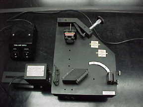
Picture 1 Picture of Michelson Interferometer. See manual for full description of the setup and parts. |
 |
|
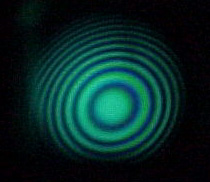
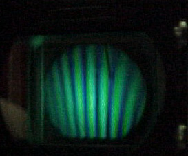
Once the mirrors are perpendicular you should see fringes that are hyperbolic in shape. Adjust the tilt controls on mirror B until the center of the fringes is in the viewer, these will look perfectly circular. By adjusting the path length control knob you can either increase or decrease the number of fringes present - fewer fringes means a small difference between the two path lengths. |
  |
|
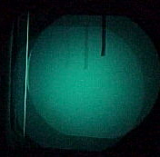
After first turning on the mercury vapor lamp this is what the reflection should look like if the mirrors are not perpendicular to each other. The pointer on the far right should be lined up with the fainter pointer that moves when you adjust the tilt controls on mirror B. When these two pointers overlap the mirrors will then be perpendicular to each other and interference fringes can be seen. |
 |
|
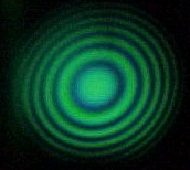
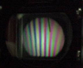
Adjust the path length by turning the path length control knob so that the circular fringes collapse towards the center. When the path lengths for the two mirrors are nearly equal, strainght interference lines should be seen. Adjust the vertical and horizontal controls on mirror B until these lines are vertical. At this time turn on the incandescent lamp as well. |
 |
|
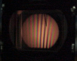
Turn the path length control knob slowly until you can see these distinctive dark fringes in the viewer. Center these fringes in the view...the path length difference between the two mirrors is now +/- 5 wavelengths. |
 |
|
Now turn off the mercury vapor lamp, leaving just the incandescent lamp on. You should still be able to see the interference pattern. Adjust the path length control knob slightly to see how sensitive these fringes are to the difference in path lengths. |
 |