Please read this note on RLC OscillationsYou may want to play with this virtual RLC circuit:
http://webphysics.ph.msstate.edu/jc/library/21-5/CircuitiE.html
In this lab you will be using an RLC circuit to become familiar with its response. A circuit diagram and picture of the setup is shown below:
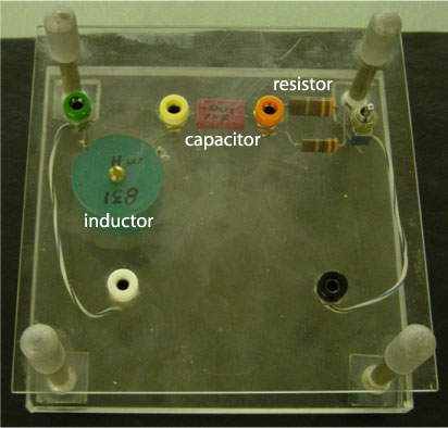
RLC
circuit - For the RLC
circuit, where the output voltage is taken across the resistor,
the ratio and output to input voltages and the phase angle depend
on frequency as:
Keep in mind that in these equations omega is the angular frequency and:
where f is in Hz -- PLEASE MAKE SURE YOU UNDERSTAND HOW TO DERIVE THE ABOVE - THERE ARE TWO RELEVANT EQUATIONS - ONE FOR THE VOLTAGE RATIO AND A SEPARATE ONE FOR THE PHASE ANGLE.
Procedure:
Using the oscilloscope measure the input voltage and the voltage across the resistor at the same time. The voltage across the resistor is essentially a measure of the current through the circuit. Determine the resonant frequency from the circuit element values. Start by setting the function generator's frequency at resonant frequency and verify that the phase and output/input ratios are correct. Then take frequency steps above and below resonance to map out the above functions for the phase and output/input ratios. Use IGOR to compare your measurements to theory. Your writeup should include plots and a discussion of your procedure.
Using Verniers on the Scope:
The scope we have set up for you has controls to position two horizontal lines to measure voltage or two vertical lines to measure time. The picture below shows that part of the scope that controls these functions and the displays on the CRT
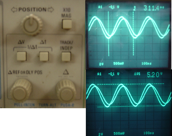
Sample scope traces: